

Hier findet ihr immer die aktuellen Bootloaderversionen (Intel-Hex-Format) für meine Mikrocontrollermodule
von dev-tools.de veröffentlichen.
In Verbindung mit der kostenlosen Windows-Software Nano Development Manager, könnt ihr Flash- und Eeprom-Memory der Mikrocontroller über USB programmieren.
(die Programmiersoftware werde ich hier der Ressource noch verlinken)
Benötigt wird noch der VCP Treiber für die USB-UART-Bridge CP2102 von Silabs. Die jeweils angegebene Fusebiteinstellung entspricht der Einstellung der Module mit Bootloader aus dem Onlineshop.
Weitere Informationen zu Nano Development Manager findet ihr hier im Forum.
MEGA128-USB

Microcontroller: ATmega128A
Fusebit Configuration:
FUSE LOW 0xFF
FUSE HIGH 0xCA
FUSE EXTENDED 0xFF
Flash: 124kByte (126976Byte)
Eeprom: 4kByte (4096Byte)
Systemclock: 16MHz
Author: Dirk
BSD License
Revision 2
Download:
Bootloader_Mega128-USB-Version2.zip
Bootloader_Mega128-USB-LED_PA0-Version2.zip
LED_PA0 Version: Bootloader set PA0 pin output, low.
MEGA2560-USB

Microcontroller: ATmega2560
Fusebit Configuration :
FUSE LOW 0xFF
FUSE HIGH 0xDA
FUSE EXTENDED 0xFF
Flash: 252kByte (258048Byte)
Eeprom: 4kByte (4096Byte)
Systemclock: 16MHz
Author: Dirk
BSD License
Revision 1
Download: Bootloader_Mega2560-USB.zip
XMEGA-A4-USB

Microcontroller: ATxmega32A4
Fusebit Configuration:
FUSEBYTE0: 0xFF
FUSEBYTE1: 0x00
FUSEBYTE2: 0xBF
FUSEBYTE4: 0xFF
FUSEBYTE5: 0xFF
Flash: 32kByte (32768Byte) Application Section
Eeprom: 1kByte (1024Byte)
Author: Dirk
BSD License
Revision 1
Download: Bootloader_Xmega-A4-USB.zip
XMEGA-A1-USB

Microcontroller: ATxmega128A1
Fusebit Configuration:
FUSEBYTE0: 0xFF
FUSEBYTE1: 0x00
FUSEBYTE2: 0xBF
FUSEBYTE4: 0xFF
FUSEBYTE5: 0xFF
Flash: 128kByte (131072 Byte) Application Section
Eeprom: 2kByte (2048Byte)
Author: Dirk
BSD License
Revision 1
Download: Bootloader_Xmega-A1-USB.zip
Die Mikrocontrollermodule mit programmiertem Bootloader, fertig konfiguriert und geprüft, sind auch im Onlineshop bestellbar.
MEGA128-USB-V2-BL
Mikrocontrollermodul mit ATmega128A
mit Bootloader
MEGA2560-USB-BL
Mikrocontrollermodul mit ATmega2560
mit Bootloader
XMEGA-A1-USB-BL
Mikrocontrollermodul mit ATxmega128A1
mit Bootloader
XMEGA-A4-USB-BL
Mikrocontrollermodul mit ATxmega32A4
mit Bootloader
Wenn die eigene Anwendung aktiv ist und man möchte erneut programmieren, muss man den Mikrocontroller resetten, damit der Bootloader wieder aktiviert wird und mit dem PC-Programm kommunizieren kann. Einige Module besitzen einen Reset-Button.
Die folgenden Beispiele zeigen euch, wie man aus der eigenen Anwendung den Bootloader starten kann. Wenn programmiert werden soll, sendet das PC-Programm ein Bootloaderkommando, die eigene Anwendung kann darauf reagieren und den Bootloader starten.
Dirk
MEGA128-USB
CodeBox C
MEGA2560-USB
CodeBox C
XMEGA-A1-USB
CodeBox C
XMEGA-A4-USB
CodeBox C
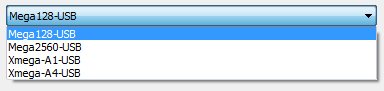
- Mega128-USB (ATmega128A),
- Mega2560-USB (ATmega2560),
- Xmega-A1-USB (ATmega128A1) und
- Xmega-A4-USB (ATmega32A4)
von dev-tools.de veröffentlichen.
In Verbindung mit der kostenlosen Windows-Software Nano Development Manager, könnt ihr Flash- und Eeprom-Memory der Mikrocontroller über USB programmieren.
(die Programmiersoftware werde ich hier der Ressource noch verlinken)
Benötigt wird noch der VCP Treiber für die USB-UART-Bridge CP2102 von Silabs. Die jeweils angegebene Fusebiteinstellung entspricht der Einstellung der Module mit Bootloader aus dem Onlineshop.
Weitere Informationen zu Nano Development Manager findet ihr hier im Forum.
MEGA128-USB
Microcontroller: ATmega128A
Fusebit Configuration:
- BOOTRST: programmed
- BOOTSZ: 4kByte, Address 0xF800
- M103C not programmed
- JTAGEN not programmed
- CKOPT programmed
- SUT CKSEL: Ext. Crystal/Resonator High Freq.; Start-up time: 16K CK + 64 ms
FUSE LOW 0xFF
FUSE HIGH 0xCA
FUSE EXTENDED 0xFF
Flash: 124kByte (126976Byte)
Eeprom: 4kByte (4096Byte)
Systemclock: 16MHz
Author: Dirk
BSD License
Revision 2
Download:
Bootloader_Mega128-USB-Version2.zip
Bootloader_Mega128-USB-LED_PA0-Version2.zip
LED_PA0 Version: Bootloader set PA0 pin output, low.
MEGA2560-USB
Microcontroller: ATmega2560
Fusebit Configuration :
- BOOTRST programmed
- BOOTSZ 4kByte, Address 0x1F800
- JTAGEN not programmed
- CKDIV8 not programmed
- SUT CKSEL Ext. Crystal Osc. 8.0- MHz; Start-up time: 16K CK + 65 ms
FUSE LOW 0xFF
FUSE HIGH 0xDA
FUSE EXTENDED 0xFF
Flash: 252kByte (258048Byte)
Eeprom: 4kByte (4096Byte)
Systemclock: 16MHz
Author: Dirk
BSD License
Revision 1
Download: Bootloader_Mega2560-USB.zip
XMEGA-A4-USB
Microcontroller: ATxmega32A4
Fusebit Configuration:
- BOOTRST: Bootloader Reset
FUSEBYTE0: 0xFF
FUSEBYTE1: 0x00
FUSEBYTE2: 0xBF
FUSEBYTE4: 0xFF
FUSEBYTE5: 0xFF
Flash: 32kByte (32768Byte) Application Section
Eeprom: 1kByte (1024Byte)
Author: Dirk
BSD License
Revision 1
Download: Bootloader_Xmega-A4-USB.zip
XMEGA-A1-USB
Microcontroller: ATxmega128A1
Fusebit Configuration:
- BOOTRST: Bootloader Reset
- JTAGEN: not programmed
FUSEBYTE0: 0xFF
FUSEBYTE1: 0x00
FUSEBYTE2: 0xBF
FUSEBYTE4: 0xFF
FUSEBYTE5: 0xFF
Flash: 128kByte (131072 Byte) Application Section
Eeprom: 2kByte (2048Byte)
Author: Dirk
BSD License
Revision 1
Download: Bootloader_Xmega-A1-USB.zip
Die Mikrocontrollermodule mit programmiertem Bootloader, fertig konfiguriert und geprüft, sind auch im Onlineshop bestellbar.
MEGA128-USB-V2-BL
Mikrocontrollermodul mit ATmega128A
mit Bootloader
MEGA2560-USB-BL
Mikrocontrollermodul mit ATmega2560
mit Bootloader
XMEGA-A1-USB-BL
Mikrocontrollermodul mit ATxmega128A1
mit Bootloader
XMEGA-A4-USB-BL
Mikrocontrollermodul mit ATxmega32A4
mit Bootloader
Wenn die eigene Anwendung aktiv ist und man möchte erneut programmieren, muss man den Mikrocontroller resetten, damit der Bootloader wieder aktiviert wird und mit dem PC-Programm kommunizieren kann. Einige Module besitzen einen Reset-Button.
Die folgenden Beispiele zeigen euch, wie man aus der eigenen Anwendung den Bootloader starten kann. Wenn programmiert werden soll, sendet das PC-Programm ein Bootloaderkommando, die eigene Anwendung kann darauf reagieren und den Bootloader starten.
Dirk
MEGA128-USB
CodeBox C
/**********************************************************************************
* This is an example how to jump from your application to bootloader.
*
* The example relates to our microcontroller module MEGA128-USB-BL.
*
*
* Recommended development environment:
*
* Atmel Studio 6
* ---> http://www.atmel.com/Microsite/atmel_studio6/default.aspx
* Nano Development Software from dev-tools.de (see Tab downloads).
* ---> http://www.dev-tools.de/index.php/development-boards/developmentboard-nano
*
* MEGA128-USB: You can purchase this microcontroller module from
* ---> http://mikrocontroller-praxis.de/de/search.html?page=search&keywords=mega128-usb&x=0&y=0
*
* We invests time and resources providing this open source code,
* please support www.avr-praxis.de and open-source hardware
* by purchasing products from www.mikrocontroller-praxis.de!
*
* Written by Dirk Rodenhausen (dirk at avr-praxis.de)
**********************************************************************************/

/*
* App_Mega128_USB.c
*
* Created: 14.04.2013 11:20:28
* Author: Dirk
*/

#define F_CPU   16000000UL

#include <avr/io.h>
#include <avr/interrupt.h>
#include <util/delay.h>


// the pointer to bootloader
void (*boot_start)(void) = 0xF800;  // word

void Bootloader_Start(void);
uint8_t USART_Receive(void);
void USART_Send(uint8_t data);
void USART_Init(void);


int main(void)
{

   USART_Init();


   while(1)
   {

     if (UCSR1A & (1<<RXC1))
     {
       Bootloader_Start();
     }

     // Application code

   }
}


void Bootloader_Start(void)
{

   cli();
   TCCR3B = 0;       // stop timer 3
   TCNT3 = 0x1234;     // message: activate bootloader by application
   boot_start();
}


uint8_t USART_Receive(void)
{

   while (!(UCSR1A & (1<<RXC1))) {};

   return UDR1;

}


void USART_Send(uint8_t data)
{

   while (!(UCSR1A & (1<<UDRE1))) {};

   UDR1 = data;

}


#define USART_UBBR_VALUE     3 // Baud rate = 250.000 bps (Error=0,0%) with fCK = 16MHz
void USART_Init(void)
{

   /* Must turn off USART before reconfiguring it, otherwise incorrect operation may occur */
   UCSR1B = 0;
   UCSR1A = 0;
   UCSR1C = 0;

  // Port Register
   PORTD |= 1<<PD3;       // TXD logic high
  PORTD &= ~(1<<PD2);       // RXD high impedance

  // Data Direction
  DDRD &= ~(1<<PD2);       // RXD Input
   DDRD |= 1<<PD3;         // TXD Output

   UBRR1L = USART_UBBR_VALUE;
   UBRR1H = (USART_UBBR_VALUE >> 8);

   UCSR1B = (1 << TXEN1) | (1 << RXEN1);
   UCSR1C = (1 <<UCSZ11) | (1 <<UCSZ10);

   uint8_t tmp = UCSR1A; // flush buffer / reset status
   tmp = UDR1;

}
MEGA2560-USB
CodeBox C
/**********************************************************************************
* This is an example how to jump from your application to bootloader.
*
* The example relates to our microcontroller module MEGA2560-USB-BL.
*
*
* Recommended development environment:
*
* Atmel Studio 6
* ---> http://www.atmel.com/Microsite/atmel_studio6/default.aspx
* Nano Development Software from dev-tools.de (see Tab downloads).
* ---> http://www.dev-tools.de/index.php/development-boards/developmentboard-nano
*
* MEGA2560-USB-BL: You can purchase this microcontroller module from
* ---> http://mikrocontroller-praxis.de/de/search.html?page=search&keywords=mega2560-usb-bl&x=0&y=0
*
* We invests time and resources providing this open source code,
* please support www.avr-praxis.de and open-source hardware
* by purchasing products from www.mikrocontroller-praxis.de!
*
* Written by Dirk Rodenhausen (dirk at avr-praxis.de)
**********************************************************************************/

/*
* App_Mega2560_USB.c
*
* Created: 09.04.2013 11:51:54
* Author: Dirk
*/

#define F_CPU   16000000UL

#include <avr/io.h>
#include <avr/interrupt.h>
#include <util/delay.h>

#define LED_PORT   PORTL
#define LED_DIR     DDRL
#define LED_PIN     PL7
#define LED_ON     LED_PORT &= ~(1<<LED_PIN);
#define LED_OFF     LED_PORT |= 1<<LED_PIN;


// the pointer to bootloader
void (*boot_start)(void) = 0x1F800;  // word
// Byte 0x258048 = 0x3F000

void Bootloader_Start(void);
uint8_t USART_Receive(void);
void USART_Send(uint8_t data);
void USART_Init(void);

int main(void)
{

   USART_Init();

   // turn on the LED to indicate the bootloader is active
   LED_DIR |= (1<<LED_PIN);
   LED_PORT |= (1<<LED_PIN);
   uint16_t pwmcounter = 0; // for the LED pulsing
   uint16_t brightness = 0; // for the LED pulsing
   int8_t pulsedirection = 1;


  while(1)
  {


       pwmcounter++;

       // after each PWM cycle, increase/decrease the brightness
       if (pwmcounter == 1000) {
         brightness += pulsedirection;
         LED_OFF
       }

       // PWM compare match
       if (pwmcounter == brightness) LED_ON


       // make the bootloade LED pulse up and down
       if (brightness == 255) pulsedirection = -1;


       if ((brightness == 0) && (pulsedirection != 1))   pulsedirection = 1;


  //TODO:: Please write your application code


     if (UCSR3A & (1<<RXC3))
     {

        Bootloader_Start();
     }
  }
}


void Bootloader_Start(void)
{

   cli();
   TCCR3B = 0;       // stop timer 3
   TCNT3 = 0x1234;     // message: activate bootloader by application
   EIND = 1;       // msb pointer bit (gcc bug workaround)
   boot_start();
}


uint8_t USART_Receive(void)
{

   while (!(UCSR3A & (1<<RXC3))) {};

   return UDR3;

}


void USART_Send(uint8_t data)
{

   while (!(UCSR3A & (1<<UDRE3))) {};

   UDR3 = data;

}


#define USART_UBBR_VALUE     3 // Baud rate = 250.000 bps (Error=0,0%) with fCK = 16MHz
void USART_Init(void)
{

   /* Must turn off USART before reconfiguring it, otherwise incorrect operation may occur */
   UCSR3B = 0;
   UCSR3A = 0;
   UCSR3C = 0;

  // Port Register
   PORTJ |= 1<<PJ0;       // TXD logic high
  PORTJ &= ~(1<<PJ1);       // RXD high impedance

  // Data Direction
  DDRJ &= ~(1<<PJ1);       // RXD Input
   DDRJ |= 1<<PJ0;         // TXD Output

   UBRR3L = USART_UBBR_VALUE;
   UBRR3H = (USART_UBBR_VALUE >> 8);

   //UCSR1A = (1 << U2X1);
   UCSR3B = (1 << TXEN3) | (1 << RXEN3);
   UCSR3C = (1 <<UCSZ31) | (1 <<UCSZ30);

   uint8_t tmp = UCSR3A; // flush buffer / reset status
   tmp = UDR3;

}
XMEGA-A1-USB
CodeBox C
/*
* App_Xmega_A1_USB.c
*
* Written for microcontroller module XMEGA-A1-USB-BL (www.dev-tools.de)
*
* Microcontroller ATxmega128A1
*
* This example code shows you how to jump to bootloader when a bootloader
* command will be received.
*
* System clock: 32MHz
* USARTE0: 8N1 250kBit
*
* Created: 12.04.2013 13:24:33
* Author: Dirk (dirk at avr-praxis.de)
*
* Links:
*
* XMEGA-A1-USB-BL microcontroller module with ATxmega128A1
* http://mikrocontroller-praxis.de/search.html?page=search&keywords=XMEGA-A1-USB-BL
* Nano Development Manager (windows platform)
* http://www.dev-tools.de/index.php/development-boards/developmentboard-nano
* Silabs CP2102 VCP driver download
* http://www.silabs.com/products/mcu/Pages/USBtoUARTBridgeVCPDrivers.aspx
*/


#define F_CPU   32000000UL
#include <avr/io.h>
#include <avr/interrupt.h>
#include <util/delay.h>

void Bootloader_Start (void);
uint8_t UsartReceiveBufferFull (void);
uint8_t UsartReceive (void);
void UsartSend (uint8_t data);
void UsartInit (void);
static void SystemClock32 (void);
static void LEDInit (void);
static void LED_On (void);
static void LED_Off (void);
void CCPWrite( volatile uint8_t * address, uint8_t value );


int main(void)
{

   SystemClock32();
   UsartInit();
   LEDInit();

  while(1)
  {

     // Nano Development Manager sends "IS" to microcontroller module
     // jump to bootloader if we receive some byte via USARTE0
     if (UsartReceiveBufferFull()) Bootloader_Start();

     //TODO:: Please write your application code
     _delay_ms(30);
     LED_On();

     _delay_ms(30);
     LED_Off();


  }
}


void Bootloader_Start (void)
{

   cli();
   TCC0.CTRLA = 0;       // stop timer C0
   TCC0.CNT = 0x1234;     // message: activate bootloader by application
   EIND = 1;         // msb pointer bit (gcc bug workaround)

   asm volatile (
   "ldi r30,0x00"  "\n\t"  //indirect call address
   "ldi r31,0x00"  "\n\t"  //16bit address z
   "eijmp" "\n\t"
   ::);

}


uint8_t UsartReceiveBufferFull (void)
{
   return (USARTF0.STATUS & USART_RXCIF_bm);
}

uint8_t UsartReceive (void)
{
   while (!(USARTF0.STATUS & USART_RXCIF_bm)) {};
   return USARTF0.DATA;
}

void UsartSend (uint8_t data)
{
   while (!(USARTF0.STATUS & USART_DREIF_bm)) {};
   USARTF0.DATA = data;
}

void UsartInit (void)
{
   /************************************************************************
   USARTF0 - Universal Asynchronous Receiver-Transmitter F0
   250kBit, 8N1
   ************************************************************************/

   PORTF.DIRSET = PIN3_bm;     // PF3: TXT Output
   PORTF.DIRCLR = PIN2_bm;     // PF2: RXD Input

   USARTF0.CTRLC = USART_CHSIZE_8BIT_gc | USART_PMODE_DISABLED_gc;
   USARTF0.CTRLA = 0;

   USARTF0.BAUDCTRLA = 7;     // BSEL
   USARTF0.BAUDCTRLB = 0;     // SCALE, BSEL

   USARTF0_CTRLB = USART_RXEN_bm | USART_TXEN_bm;

   uint8_t data = USARTF0.DATA;

}


static void SystemClock32 (void)
{
   /************************************************************************
   System Clock 32MHz
   (XOSC Quartz 16MHz, PLL Factor 2)
   ************************************************************************/

   OSC.XOSCCTRL = OSC_FRQRANGE_12TO16_gc | OSC_XOSCSEL_XTAL_256CLK_gc;

   OSC.CTRL |= OSC_XOSCEN_bm;

   while (!(OSC_STATUS & OSC_XOSCRDY_bm)) {};

   OSC.PLLCTRL = OSC_PLLSRC_XOSC_gc | 2;

   OSC.CTRL |= OSC_PLLEN_bm;

   CCPWrite( &CLK.PSCTRL, CLK_PSADIV_1_gc | CLK_PSBCDIV_1_1_gc);

   while (!(OSC.STATUS & OSC_PLLRDY_bm)) {};

  uint8_t i = CLK.CTRL & ~CLK_SCLKSEL_gm | CLK_SCLKSEL_PLL_gc;

   CCPWrite( &CLK.CTRL, i);

}


static void LEDInit (void)
{
  PORTQ_DIRSET = PIN3_bm;     // PQ3: Output, high
  PORTQ_OUTSET = PIN3_bm;
}

static void LED_On (void)
{
  PORTQ.OUTCLR = PIN3_bm;
}

static void LED_Off (void)
{
  PORTQ.OUTSET = PIN3_bm;
}

void CCPWrite( volatile uint8_t * address, uint8_t value )
{

   uint8_t volatile saved_sreg = SREG;
  cli();

   #ifdef __ICCAVR__

   asm("movw r30, r16");
   #ifdef RAMPZ
   RAMPZ = 0;
   #endif
   asm("ldi  r16,  0xD8 \n"
   "out  0x34, r16  \n"
   #if (__MEMORY_MODEL__ == 1)
   "st  Z,  r17  \n");
   #elif (__MEMORY_MODEL__ == 2)
   "st  Z,  r18  \n");
   #else /* (__MEMORY_MODEL__ == 3) || (__MEMORY_MODEL__ == 5) */
   "st  Z,  r19  \n");
   #endif /* __MEMORY_MODEL__ */

   #elif defined __GNUC__
   volatile uint8_t * tmpAddr = address;
   #ifdef RAMPZ
   RAMPZ = 0;
   #endif
   asm volatile(
   "movw r30,  %0"    "\n\t"
   "ldi  r16,  %2"    "\n\t"
   "out  %3, r16"    "\n\t"
   "st  Z,  %1"  "\n\t"
   :
   : "r" (tmpAddr), "r" (value), "M" (CCP_IOREG_gc), "i" (&CCP)
   : "r16", "r30", "r31"
   );

   #endif

   SREG = saved_sreg;

}
XMEGA-A4-USB
CodeBox C
/*
* App_Xmega_A4_USB.c
*
* Written for microcontroller module XMEGA-A4-USB-BL (www.dev-tools.de)
*
* Microcontroller ATxmega32A4
*
* This example code shows you how to jump to bootloader when a bootloader
* command will be received.
*
* System clock: 32MHz
* USARTE0: 8N1 250kBit
*
* Created: 13.04.2013 13:33:04
* Author: Dirk (dirk at avr-praxis.de)
*
* Links:
*
* XMEGA-A4-USB-BL microcontroller module with ATxmega32A4
* http://mikrocontroller-praxis.de/search.html?keywords=XMEGA-A4-USB-BL
* Nano Development Manager (windows platform)
* http://www.dev-tools.de/index.php/development-boards/developmentboard-nano
* Silabs CP2102 VCP driver download
* http://www.silabs.com/products/mcu/Pages/USBtoUARTBridgeVCPDrivers.aspx
*/


#define F_CPU   32000000UL
#include <avr/io.h>
#include <avr/interrupt.h>
#include <util/delay.h>

void Bootloader_Start (void);
uint8_t UsartReceiveBufferFull (void);
uint8_t UsartReceive (void);
void UsartSend (uint8_t data);
void UsartInit (void);
static void SystemClock32 (void);
static void LEDInit (void);
static void LED_On (void);
static void LED_Off (void);
void CCPWrite( volatile uint8_t * address, uint8_t value );


int main(void)
{

   SystemClock32();
   UsartInit();
   LEDInit();

  while(1)
  {

     // Nano Development Manager sends "IS" to microcontroller module
     // jump to bootloader if we receive some byte via USARTE0
     if (UsartReceiveBufferFull()) Bootloader_Start();


  //TODO:: Please write your application code
     _delay_ms(30);
     LED_On();

     _delay_ms(30);
     LED_Off();


  }
}


void Bootloader_Start (void)
{

   cli();
   TCC0.CTRLA = 0;       // stop timer C0
   TCC0.CNT = 0x1234;     // message: activate bootloader by application
   EIND = 0;         // msb pointer bit (gcc bug workaround)

   asm volatile (
   "ldi r30,0x00"  "\n\t"  //indirect call address
   "ldi r31,0x40"  "\n\t"  //16bit address z
   "ijmp" "\n\t"
   ::);

}


uint8_t UsartReceiveBufferFull (void)
{
   return (USARTE0.STATUS & USART_RXCIF_bm);
}

uint8_t UsartReceive (void)
{
   while (!(USARTE0.STATUS & USART_RXCIF_bm)) {};
   return USARTE0.DATA;
}

void UsartSend (uint8_t data)
{
   while (!(USARTE0.STATUS & USART_DREIF_bm)) {};
   USARTE0.DATA = data;
}

void UsartInit (void)
{
   /************************************************************************
   USARTE0 - Universal Asynchronous Receiver-Transmitter E0
   250kBit, 8N1
   ************************************************************************/

   PORTE.DIRSET = PIN3_bm;     // PE3: TXT Output
   PORTE.DIRCLR = PIN2_bm;     // PE2: RXD Input

   USARTE0.CTRLC = USART_CHSIZE_8BIT_gc | USART_PMODE_DISABLED_gc;
   USARTE0.CTRLA = 0;

   USARTE0.BAUDCTRLA = 7;     // BSEL
   USARTE0.BAUDCTRLB = 0;     // SCALE, BSEL

   USARTE0_CTRLB = USART_RXEN_bm | USART_TXEN_bm;

   uint8_t data = USARTE0.DATA;

}


static void SystemClock32 (void)
{
   /************************************************************************
   System Clock 32MHz
   (XOSC Quartz 16MHz, PLL Factor 2)
   ************************************************************************/

   OSC.XOSCCTRL = OSC_FRQRANGE_12TO16_gc | OSC_XOSCSEL_XTAL_256CLK_gc;

   OSC.CTRL |= OSC_XOSCEN_bm;

   while (!(OSC_STATUS & OSC_XOSCRDY_bm)) {};

   OSC.PLLCTRL = OSC_PLLSRC_XOSC_gc | 2;

   OSC.CTRL |= OSC_PLLEN_bm;

   CCPWrite( &CLK.PSCTRL, CLK_PSADIV_1_gc | CLK_PSBCDIV_1_1_gc);

   while (!(OSC.STATUS & OSC_PLLRDY_bm)) {};

  uint8_t i = CLK.CTRL & ~CLK_SCLKSEL_gm | CLK_SCLKSEL_PLL_gc;

   CCPWrite( &CLK.CTRL, i);

}


static void LEDInit (void)
{
  PORTA_DIRSET = PIN7_bm;     // PA3: Output, high
  PORTA_OUTSET = PIN7_bm;
}

static void LED_On (void)
{
  PORTA.OUTCLR = PIN7_bm;
}

static void LED_Off (void)
{
  PORTA.OUTSET = PIN7_bm;
}

void CCPWrite( volatile uint8_t * address, uint8_t value )
{

   uint8_t volatile saved_sreg = SREG;
  cli();

   #ifdef __ICCAVR__

   asm("movw r30, r16");
   #ifdef RAMPZ
   RAMPZ = 0;
   #endif
   asm("ldi  r16,  0xD8 \n"
   "out  0x34, r16  \n"
   #if (__MEMORY_MODEL__ == 1)
   "st  Z,  r17  \n");
   #elif (__MEMORY_MODEL__ == 2)
   "st  Z,  r18  \n");
   #else /* (__MEMORY_MODEL__ == 3) || (__MEMORY_MODEL__ == 5) */
   "st  Z,  r19  \n");
   #endif /* __MEMORY_MODEL__ */

   #elif defined __GNUC__
   volatile uint8_t * tmpAddr = address;
   #ifdef RAMPZ
   RAMPZ = 0;
   #endif
   asm volatile(
   "movw r30,  %0"    "\n\t"
   "ldi  r16,  %2"    "\n\t"
   "out  %3, r16"    "\n\t"
   "st  Z,  %1"  "\n\t"
   :
   : "r" (tmpAddr), "r" (value), "M" (CCP_IOREG_gc), "i" (&CCP)
   : "r16", "r30", "r31"
   );

   #endif

   SREG = saved_sreg;

}